Online Message
Code
Refrigerated Special Gas Dryer
Special gas drying mainly refers to gases such as biogas, natural gas, hydrogen, coalbed methane (gas), associated gas, carbon dioxide, and organic waste gases. The operating pressure is generally -10 kPa to 2.5 MPa. After being dehydrated by a refrigerated dryer, these gases are sent to generators or other equipment, protecting downstream devices from damage caused by excessive moisture. This process allows the gases to generate power while protecting the environment and meeting energy-saving and emission reduction requirements. Since 2006, our company has been the first in China to develop this product, which has been widely applied in industries such as waste-to-energy, oilfields, environmental protection, steel, and brewing, filling a domestic gap and receiving widespread acclaim.

Process flow diagram


Working Principle

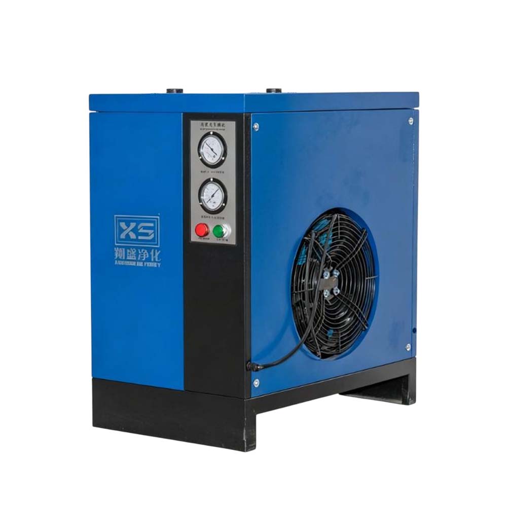
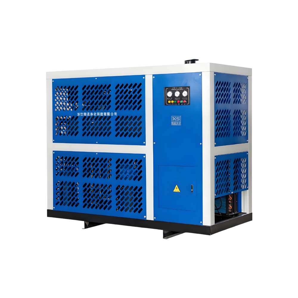
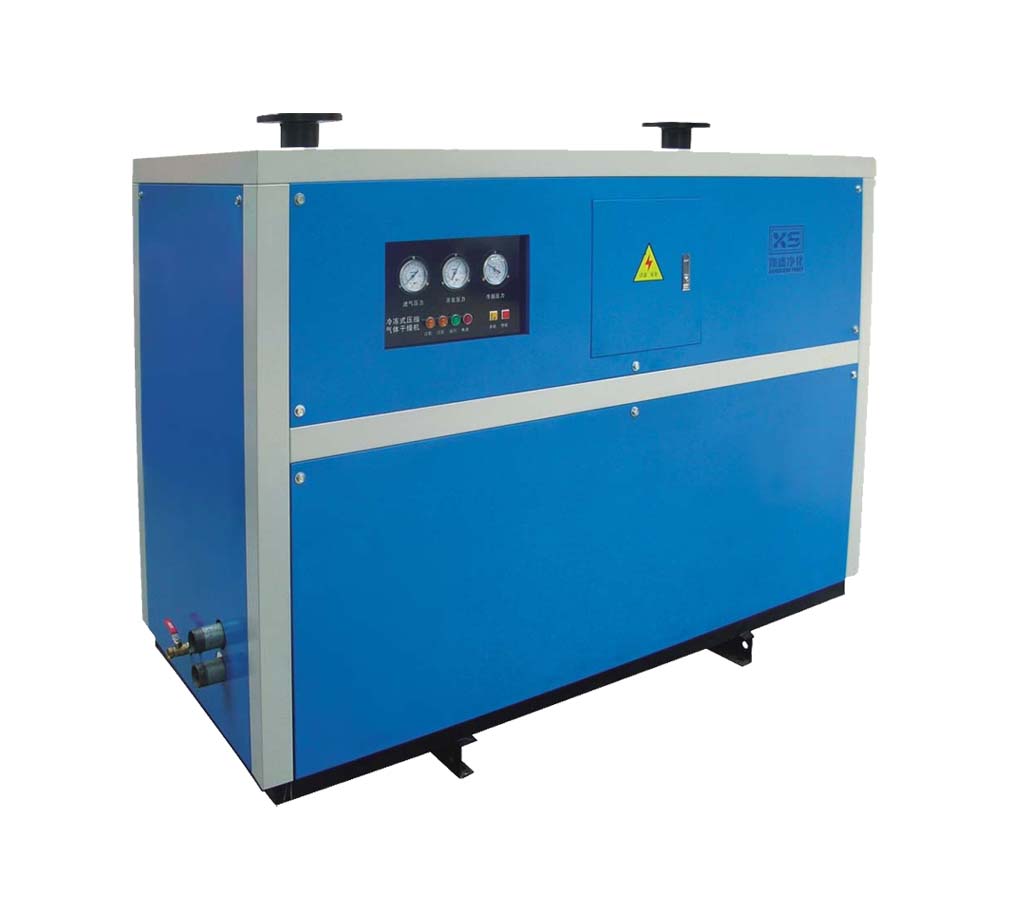
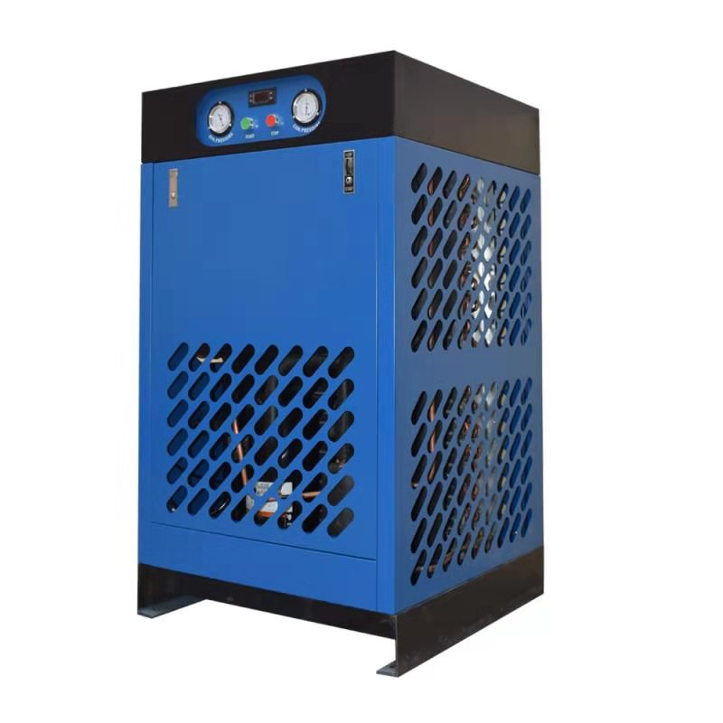
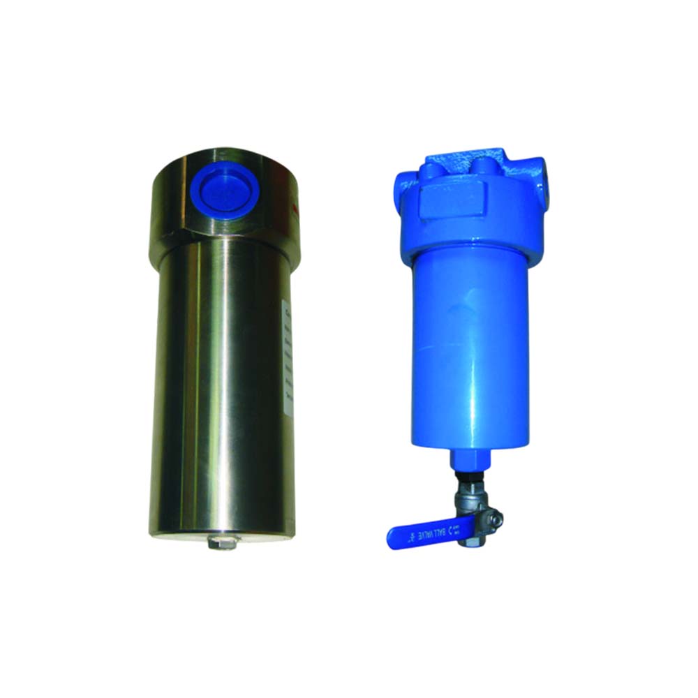
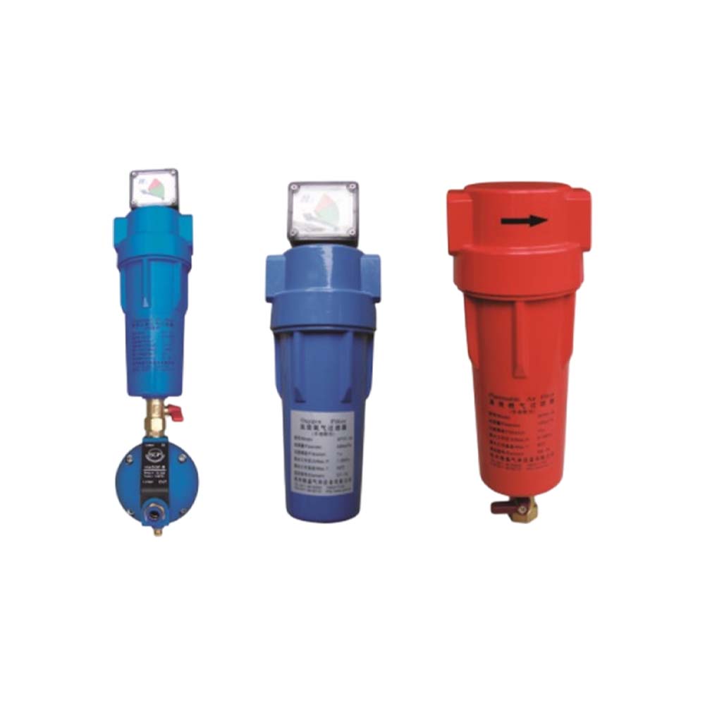
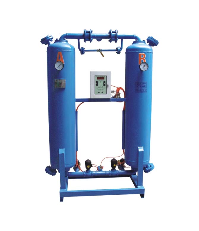
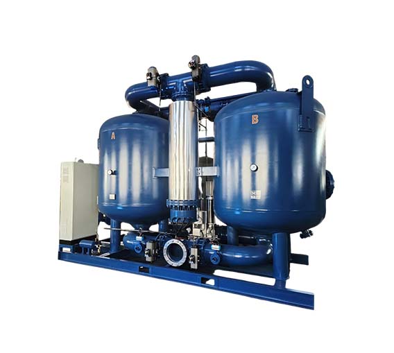
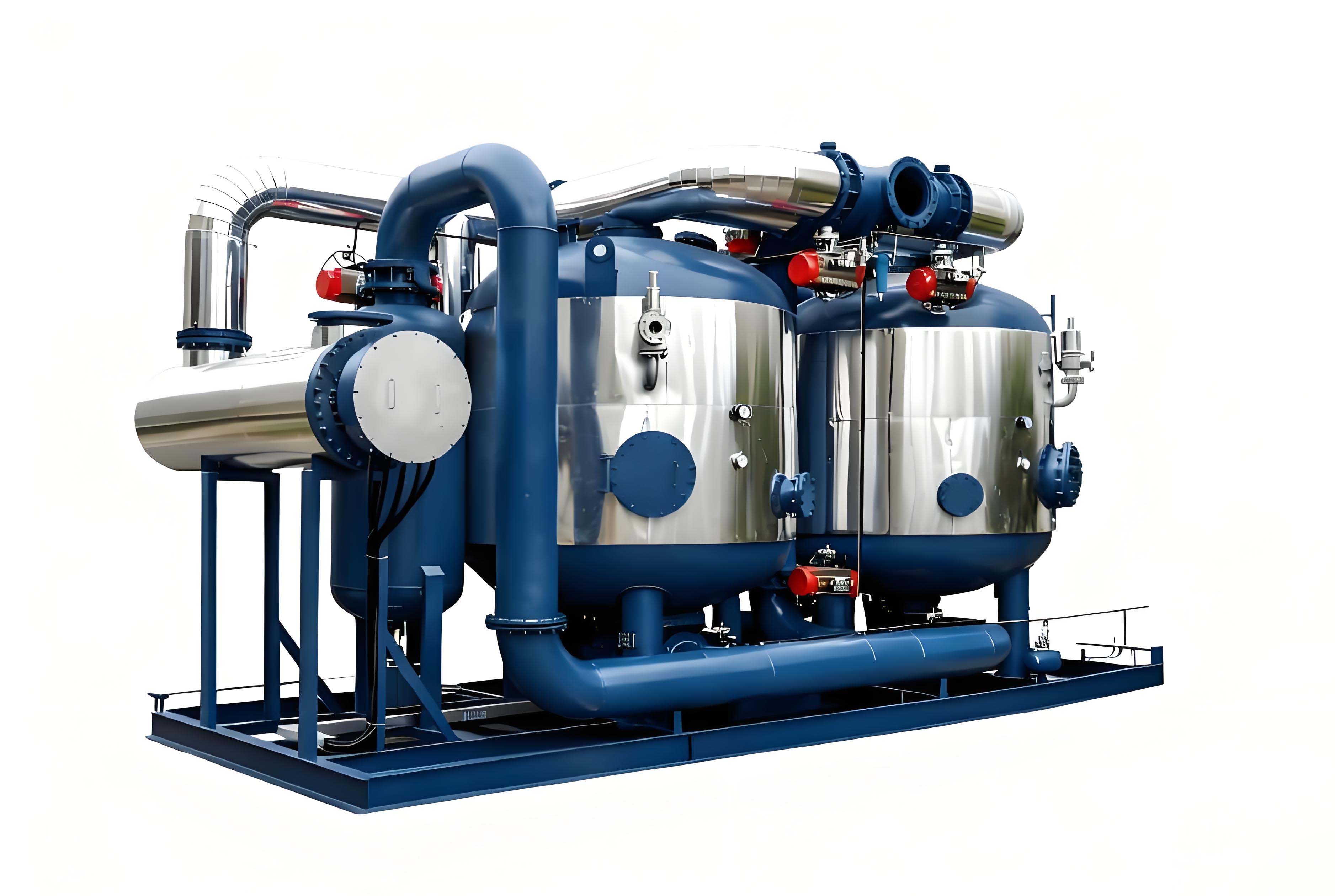
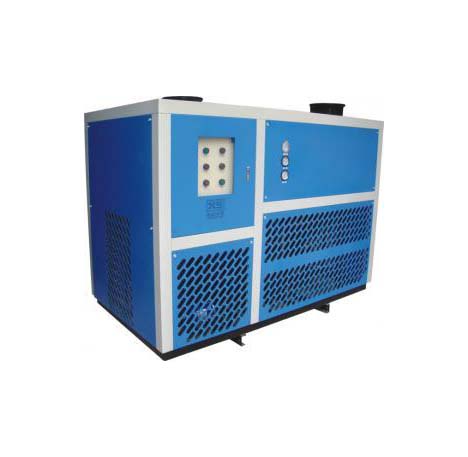
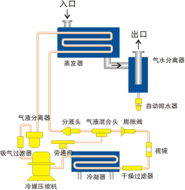
The refrigerated special gas dryer operates on the principle of refrigerated dehumidification. It uses a fully enclosed compression refrigeration system to cool low-pressure gas, causing the large amount of saturated water vapor and oil mist in the gas to condense into liquid droplets. These droplets are separated through a gas–water separator and discharged via an automatic drain. Higher-temperature saturated gas enters the evaporator of the refrigerated dryer and exchanges heat with the refrigerant vapor, lowering its temperature close to the refrigerant’s evaporation temperature. During this cooling process, water vapor condenses into liquid droplets and enters the gas–water separator. The separated liquid is discharged outside by the automatic drain, resulting in dry gas with low moisture content (i.e., low dew point) and low relative humidity at the dryer’s outlet.

Product Features

  • The refrigeration and air systems are precisely calculated by experts, with design parameters retaining over 20% margin.
  • The refrigeration compressor uses internationally advanced rotary, scroll, piston fully enclosed compressors or semi-enclosed compressors (above 20HP), providing stable operation, low noise, reliable performance, energy-saving, long service life, high energy efficiency, and IP54 protection (dust and splash proof).
  • Heat exchangers and condensers use high-quality copper tubes with pure aluminum fins; the baffled structure ensures high heat exchange efficiency, resulting in compact size. The shell material is stainless steel or galvanized carbon steel to avoid secondary contamination of compressed air.
  • Refrigeration control components use top global brands such as Danfoss (Denmark), Sporlan (USA), and Emerson, featuring excellent performance, thermal expansion valve throttling, hot gas bypass energy adjustment, overcurrent and overload protection, and high/low refrigerant pressure protection.
  • Gas–liquid separators combine cyclone separation with stainless steel mesh demisting, ensuring thorough separation, preventing secondary evaporation, and guaranteeing drying efficiency. This design outperforms standard cyclones and is more cost-effective than filter-type separators.
  • Water-cooled condensers use high-quality low-fin copper tubes with slow, multi-pass water flow for high efficiency and minimal scaling over long-term use.
  • Automatic electric-heated drains activate below 7℃, providing energy-efficient drainage (optional).
  • External rotor explosion-proof cooling fans offer high airflow, low noise, and long life with frequent starts and stops (for air-cooled models).
  • Pressure-bearing components are manufactured, tested, and inspected according to GB150-2024 “Steel Pressure Vessels” and GB151-1999 “Shell-and-Tube Heat Exchangers,” and comply with the “Technical Supervision Regulations for Pressure Vessels.”
  • The equipment structure is reasonably designed for easy maintenance; no foundation installation is required. The system has low maintenance, no consumables, low operating cost, and can run continuously without supervision.

Technical Parameters

  • Gas inlet pressure: -10~30 kPa or higher
  • Gas inlet temperature: ≤60℃
  • Gas outlet temperature: ≤20℃ or with reheating
  • Pressure dew point: 2–10℃ (approximately 6 g/m³)
  • Pressure loss: ≤0.5–3 kPa
  • Refrigerant: R-22 or optionally R134a, R404a, R407C, R410a, or other eco-friendly non-fluorinated refrigerants according to customer requirements
  • Cooling method: air-cooled or water-cooled
  • Operating voltage: 220V or 380V (customized for foreign power supply)
  • Ambient temperature: ≤40℃ (air-cooled)
  • Cooling water inlet temperature: ≤32℃ (water-cooled)
  • Cooling water inlet pressure: 0.15–0.4 MPa (water-cooled)
  • Explosion-proof rating: ExdⅡBT4 or ExdⅡCT4
  • Evaporator shell: carbon steel, SUS304, or SUS316L stainless steel
  • Evaporator core: SUS304 or SUS316L stainless steel tube with stainless steel fins or stainless steel tube structure

Model Specifications and Performance Parameters

Model / ItemXS-3A*XS-6A*XS-8A*XS-12A/W*XS-15A/W*XS20A/W*XS-25A/W*XS-30A/W*XS-40A/W*XS-50A/W*XS-60A/W*XS-80A/W*XS-100A/W*XS-120A/W*XS-150A/W*XS-200A/W*XS-250A/W*XS-300A/W*XS-350W*XS-400W*XS-500W*
Nominal Volume Flow Rate(m3/h)2040601001502403004005006008001000120015002000240030003600400045006000
Voltage(V)220V380V
Refrigeration Capacity(KW)0.891.21.552.342.563.704.505.807.509.0010.5312.4015.4019.3623.3030.7038.5051.4056.0063.0079.60
Fan Power(W)120180120*2180*2250*2450*2250*3450*3750*3750*31100*31100*31100*41100*61100*61100*81100*8----
Cooling Water Circulation Rate
(m3/h)
---233.54.35.17.28.710.313151820283542456078
Gas Connection DiameterDN40DN40DN50DN65DN80DN80DN100DN100DN125DN125DN150DN150DN200DN200DN250DN250DN300DN300DN350DN350DN400
Cooling Water Pipe Diameter--RC1"RC1"RC1"RC11/2"RC11/2"RC11/2"RC11/2"RC11/2"RC11/2"RC2"RC2"RC21/2″RC21/2"DN80DN80DN100DN125DN125DN125
Equipment Net Weight(Kg)150200230300380500550750850100013001500175021002400300032003500380040004400
Length(mm)8009501020118016501870205022002200240024502700290030003300380038004000428045004600
Width(mm)68077083085011001090113010001250125013001450160016501750175026201550155015501550
Height(mm)8409501150115012001350149015301680170017801780179017901790189026002500255025502640


Notes:

    • The above selection is based on preliminary calculations (pressure at 10 KPa). If operating conditions, pressure, flow, temperature, etc., change, re-selection is required.
    • "*" indicates the gas medium, for example: "Z" for biogas, "T" for natural gas, "R" for fuel gas, "M" for coal gas, "W" for methane gas, "Q" for hydrogen, "O" for carbon dioxide, "B" for explosion-proof type, "D" for low-pressure gas, etc.
    • Special requirements such as oversized units, liquid level drainage, adsorption dryers, process gas chiller units, and pre-treatment skids are available for custom orders.
    • If technical parameters change, the actual product shall prevail without further notice.