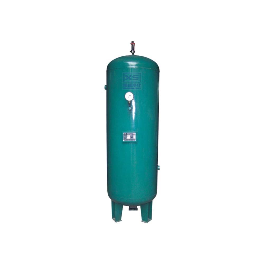
The air receiver tank can store a certain volume of compressed air, providing the pipeline with a short-term supply to complete necessary pneumatic operations when the air compressor stops. Additionally, it can eliminate the pressure pulsations of reciprocating compressors, stabilizing the air supply pressure. Users can select the tank capacity based on the required storage volume using the following formula:
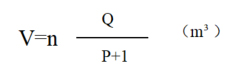
V – Air receiver tank volume (m³)
Q – Air compressor discharge volume (m³/min)
P – Air pressure (kg/cm²)
n – Tank coefficient, generally taken as 1–3
| Volume (m³) | 0.3 | 0.6 | 1.0 | 1.5 | 2.0 | 2.5 | 3.0 | 4.0 | 5.0 |
| Inner diameter (mm) × Height (mm) | 550*1594 | 700*1907 | 800*2327 | 900*2564 | 1000*2786 | 1000*3306 | 1200*2946 | 1400*3032 | 1400*3702 |
| Volume (m³) | 6.0 | 8.0 | 10 | 12 | 15 | 20 | 25 | 30 | 40 |
| Inner diameter (mm) × Height (mm) | 1400*4332 | 2000*3156 | 2000*3756 | 2000*4356 | 2200*4533 | 2400*5250 | 2400*6150 | 2500*6710 | 2500*8890 |
Note:
1. Working pressures are available in 0.8 MPa, 1.0 MPa, 1.3 MPa, 1.6 MPa, 2.5 MPa, 3.0 MPa, 4.0 MPa, 6.0 MPa, etc., and can be selected according to requirements.
2. Tank materials include carbon steel, low-alloy steel, and stainless steel. For volumes of 0.3 m³–2 m³, inlet and outlet connections can be threaded or flanged, based on user preference.
3. Detailed dimensions are provided in attached drawings; the actual product shall prevail.