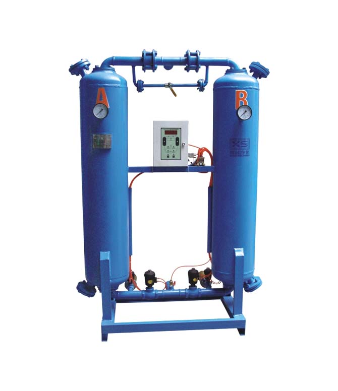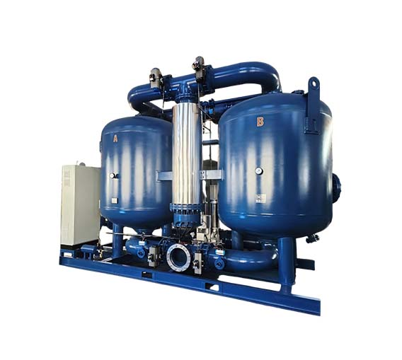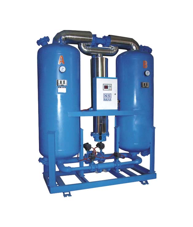
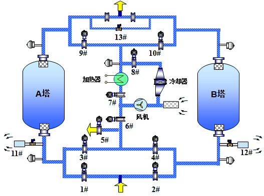
Taking Tower A in drying mode and Tower B in heated regeneration mode as an example — compressed air enters, and the pneumatic inlet switching valve (No. 1) opens. The wet compressed air flows into Tower A for drying and then passes through the exhaust check valve to output dry air. Tower B undergoes heated regeneration: the blower draws in ambient air, which passes through the heater and is heated. The regenerated air flows through the regeneration valve (No. 10) into Tower B, removing moisture from the desiccant to regenerate it. Finally, the air is discharged through the exhaust pneumatic valves (No. 4–5). As heating continues, the temperature in Tower B gradually rises. After a set heating period, the heater powers off, and the regenerated air is cooled in a closed-loop cycle — this is the cooling phase. The system operates stably according to the preset cycle.
| Model XS- | 15 GXF | 20 GXF | 25 GXF | 30GXF | 40 GXF | 50 GXF | 60 GXF | 80 GXF | 100 GXF | 120 GXF | 150 GXF | 200 GXF | 250 GXF | 300 GXF | 350 GXF | |
| Nominal Volume Flow Rate (m3/min) | 17 | 22 | 27 | 32 | 45 | 55 | 65 | 85 | 110 | 130 | 160 | 210 | 260 | 320 | 360 | |
| Heating Power (KW) | 12 | 15 | 18 | 21 | 25 | 30 | 40 | 45 | 55 | 78 | 90 | 110 | 130 | 150 | 180 | |
| Blower Power (KW) | 4.0 | 4.0 | 5.5 | 5.5 | 7.5 | 7.5 | 9.0 | 11 | 13 | 25 | 25.8 | 34.5 | 43.2 | 51.8 | 59.2 | |
| Overall Dimensions(mm) | Length | 2100 | 2100 | 2130 | 2230 | 2400 | 2620 | 2720 | 2850 | 3000 | 3560 | 3700 | 3900 | 4300 | 4800 | 5500 |
| Width | 1200 | 1200 | 1250 | 1350 | 1580 | 1650 | 1870 | 1950 | 1980 | 2400 | 2500 | 2600 | 2700 | 2850 | 3100 | |
| Height | 2100 | 2200 | 2258 | 2540 | 2700 | 2820 | 2830 | 2850 | 2950 | 3050 | 3100 | 3200 | 3300 | 3400 | 3600 | |
| Inlet and Outlet Pipe Size | DN65 | DN80 | DN80 | DN80 | DN100 | DN100 | DN125 | DN125 | DN150 | DN150 | DN200 | DN200 | DN200 | DN250 | DN300 | |
| Cooling Water Flow | 2.5 | 3.0 | 3.5 | 4.0 | 5.5 | 7.0 | 8.0 | 10.0 | 12.5 | 15.0 | 19.0 | 27.0 | 33.0 | 39.0 | 45.0 | |
| Weight(kg) | 1300 | 1500 | 1850 | 2200 | 2800 | 3230 | 4000 | 5450 | 6420 | 7150 | 9350 | 11400 | 14200 | 16800 | 19000 | |
Note:
1. Optional configurations: 1) Dew point meter, 2) Dew point control function, 3) False action alarm, 4) Bypass piping for the entire unit, 5) Front/rear filters installed on the unit, 6) PLC, touch screen, and other components from brands such as Siemens or ABB, 7) Communication options from RS485 I/O, Profibus, Modbus to Ethernet.
2. Customization is available for inlet air pressures exceeding 1.0 MPa, all-stainless-steel construction, steam or other waste heat heating methods, non-compressed-air media handling, and other special applications.
3. Technical parameters are subject to change; the actual product shall prevail without further notice.
| Correction factor | |||||||
| Operating pressure temperature (℃) | 0.45MPa | 0.5MPa | 0.6MPa | 0.7MPa | 0.8MPa | 0.9MPa | 1.0MPa |
| ≤35 | 0.67 | 0.74 | 0.86 | 1.00 | 1.09 | 1.21 | 1.33 |
| 40 | 0.51 | 0.56 | 0.65 | 0.74 | 0.83 | 0.93 | 1.02 |
| 45 | 0.40 | 0.43 | 0.50 | 0.57 | 0.64 | 0.71 | 0.78 |
| 50 | 0.31 | 0.34 | 0.39 | 0.45 | 0.50 | 0.55 | 0.61 |